

Hydraulic Pump
Hyspecs provides a full range of hydraulic pump with a brief explanation of each hydraulic pump in the following article.
Contact Hyspecs
Looking to buy a hydraulic pump or spare parts? Browse our range of pumps here or give us a call now on 1800 497 732.
Hydraulic Pump - Gear category
Consist essentially of two intermeshing toothed gears enclosed in a common housing. A shaft, the drive shaft, extends beyond the housing. This shaft is attached to one of the gears which, when it is turned by the shaft, drives the second gear. The hydraulic fluid is trapped in the gaps between the gear teeth and propelled along the inside of the housing from the suction inlet port to the pressure outlet port. The vacuum required in the suction chamber for drawing in the fluid is generated by the increase in volume which results when one of the gear teeth and its mating tooth space go out of mesh. In the pressure chamber, the teeth and their mating spaces come into mesh again and force the fluid out through the outlet port. The delivery flow is subject to pulsation effects which is one of the reason gear hydraulic pump are noisier than their vane and piston counterparts.

Hydraulic Pump - Vane category
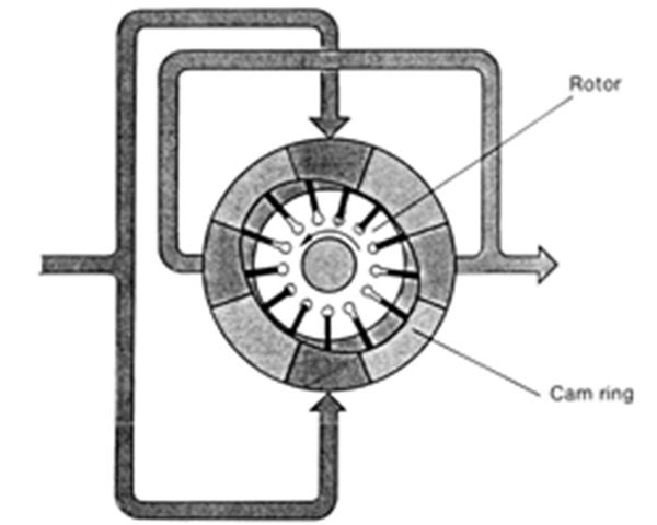
Fixed displacement: In this type of hydraulic pump, vanes are fitted in radial slots around the periphery of the driven hydraulic pump rotor. When the rotor turns, these vanes are forced outwards against the surface of the cam ring due to centrifugal force and also due to the fact that they are subject to pressure from within. The cam ring is in the form of an ellipse, with the result that two inlet (suction) chambers are formed and two outlet (pressure) chambers. The suction chambers are diametrically opposite to each other as are the pressure chambers. This means that the radial bearing forces of the rotor are compensated for. The separation of suction and pressure chambers (better known as "kidneys") is by means of control slots in the port plates fitted on the end faces of the rotor. From these plates, passages lead in the housing to the pressure and suction ports.
Hydraulic Pump - Piston category
Axial piston pumps are displacement machines in which the pistons are arranged in parallel to the axis of rotation of a cylinder barrel. The conversion of the rotating drive motion into a backwards and forwards movement of the pistons takes place in accordance with 3 main principles. These are described in the following: All versions are suitable for both pump and motor operation.
Swash-Plate Hydraulic Pump: In this version, the cylinder barrel is driven and, as a result, the pistons which are located and guided in the barrel rotate with it. In the axial direction, the movement of the pistons is determined by the swash-plate which is attached to the pump housing. This swash-plate can be pivoted with reference to the vertical axis passing through the drive shaft. The hydraulic pump displacement volume is determined by the angle at which the swash-plate is inclined from the vertical. This principle makes it possible for the hydraulic pump to be reversible. In the case of constant-capacity hydraulic pump and motors, the swash-plate angle is not variable. During the suction phase, the pistons move out of the barrel and are forced against the swash plate by a special retaining plate. During the pressure phase, the swash plate forces the pistons back into the barrel. The rotating pistons move in an elliptical orbit against the stationary swash plate. Friction is held to an absolute minimum by slipper pads or axial bearings. A form of slot control is used to ensure that the delivery flow from the individual pistons is in the same direction, and that the piston ports are connected to the pressure or suction connection at the right moment. The slot control is located in a stationary control plate against which the cylinder barrel rotates with its piston port face.

Bent Axis Hydraulic Pump: With this type of hydraulic pump, the cylinder barrel is driven by the pistons which in turn are themselves driven by the drive flange. The cylinder barrel is located and guided at its periphery by either a centre pin or a needle bearing, and is pivoted with reference to the shaft horizontal axis. The displacement volume changes in accordance with this pivot angle. Reversible hydraulic pump can be realised using this principle.
The pistons and the drive flange are connected by means of a ball·joint connection. This pulls out the pistons during the suction phase and forces them back into the piston bores in the cylinder during the pressure phase. A further knuckle joint is necessary between the actual pistons themselves and the ball-joint connection. (Compensation of the elliptical orbit and the circular orbit.) The separation of the suction and pressure sides is by means of a slot control as in the bent-axis hydraulic pump. The control plate, which can be either flat or spherical depending upon the particular design, pivots together with the cylinder barrel. In other words, the pressure connection must be routed through the swivel bearing. Oil is drawn in during the suction phase directly from the hydraulic pump chamber (this applies for versions with only one direction of delivery).

Wobble-Plate Hydraulic Pump: With this type of hydraulic pump, a so-called wobble plate is driven by the input or drive shaft. This plate transfers its axial movement to the non·rotating pistons. Springs force the pistons against the wobble plate. A thrust bearing transfers the pressure forces between the pistons and the wobble plate which are moving against each other. Valves can be used to ensure that the delivery flow from the individual pistons is in the same direction. A slot-type control at the individual pistons can also be used for this purpose. The angle of tilt of the wobble plate cannot be varied in this pump. This means that the displacement is constant.
For more information on Hyspecs hydraulic pump range talk with one of our engineers on 1800 497 732.
For servicing of your hydraulic pump call us now on 1800 497 732.
